Przeskocz do treści Przeskocz do menu

Quazar 700

Quazar 700

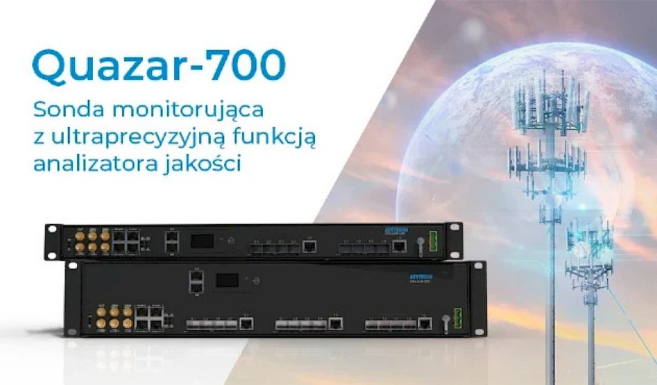
The rapidly evolving 5G network presents new challenges associated with the +/- 1.5 μs accuracy regime within the concession, determines the need to monitor time and frequency synchronization inside the telecommunications infrastructure. Reading the ITU-T G Suppl. 68, we see the inevitable need to implement a synchronization monitoring system in 5G networks. To meet the recommendations and expectations of the market, Bitstream presents the Quazar-700 monitoring probe with the QuazarNet system for analyzing data acquired from monitoring probes.

See video

Monitoring Probe to monitor network synchronization quality with time server function

Features and benefits

  • Quazar-700 enables monitoring of time and frequency synchronization in the Radio Access Network (RAN), ensuring stable and efficient network operation. This allows operators to provide high-quality services to their customers.
  • The device enables quick detection of PTP/SyncE failures (location and cause), resulting in a fast response from the operator and minimal repair costs. Quazar-700 enables operators to achieve high service availability.
  • Monitoring probe allows calibration, resulting in high time precision. This enables the provision of new types of services offered by 5G networks, especially IoT (Internet of Things), autonomous vehicles, and more.
  • The solution allows for measurement of inaccuracy parameters in existing DWDM infrastructure, allowing for the measurement and correction of cTE and asymmetry values. This leads to investment cost savings.
  • Quazar-700 can be used as a portable monitoring probe, offering flexible monitoring scenarios. Operators can monitor time and frequency synchronization in different parts of the network, resulting in quick problem resolution.

Data sheet

Manageable probe Quazar 700

Product card

Haven’t found the answers to your questions?

  • Option available after contact with manufacturer V 1.02 General specification of supported standards and protocols
    IEEE 802.3u 100Base-TX Ethernet
    IEEE 802.3ab 1000Base-T
    IEEE 802.3z Gigabit Fiber
    IEEE 802.3ae 10GBASE-SR/LR/ER/ZR (SFP+) 10 Gigabit Ethernet
  • Network Monitoring and Network Synchronization
    The device can be equipped with an on-board generator OCXO or DOCXO or RUBID

    Synchronisation signals

    • 1 x PPS_IN and 1 or 4 x PPS_OUT;
    • 1 x 10MHz_IN and 10MHz_OUT
    • 1 x E1 G703/G.704
    • 1x ToD_IN/ToD_OUT
    • 2 or 4x IRIG-B DLCS
    • 2 or 4 x IRIG-B AM 1kHz
    • 2 x PPS ST FO 850nm

    Supported synchronization protocols

    • NTP and SNTP
    • ToD
    • SSM
    • Sabits
    • NEMEA
    • NTRIP
    • RTCM
    • IRIG-B

    The following IEEE1588 v.2 (PTPv.2)-based precision time synchronization profiles are hardwaresupported on the device: Default1588, G.8265.1, G.8275.1 and G.8275.2

      • MC (Master Clock) time error typowo 40ns
      • BC (Boundry Clock) z time error z SyncE typowo <100ns
    Monitoring of possible Spoofing and Jamming interference for GNSS module
    PTP datasets (logging minimum: GrandmastrID, clock class, clock accuracy, priority2, steps
    removed)
    Real-time monitoring of TE (Time error) and MTIE (Time Interval Error) for PTPv2 and SyncE
    Presentation of real-time TE (time error) graphs in GUI (www) for PTP and SyncE
    Automatic creation of measurement data files with the possibility of archiving the data in the local
    memory of the device.
    Dedicated QUAZARNET software – optional system to extend diagnostics and visualization of
    measurement data

    The following features are available under the license:

    • PPS & ToD monitoring in ITU G.827 format 1
    • RFC2544 performance tests and ITU-T Y.1564 service tests with MPLS-TPa protocol support
    • PTP v2 synchronization with IEC 61850-9-3, IEEE C37.238-2011 or 2017 profiles
    • Synchronous Ethernet, G.8261, G.8262, G.8264
  • Module GNSS
    Antenna input with support for active antennas with SMA connector
    RS422 interface of ToD (Time-of-Day) signal with RJ45 connector, input and input sig
    Coax interface (PPS) with SMA connector, input and input signal
    GNSS multi-band receiver that works with systems GPS, GLONASS, BeiDou, Galileo
    GPS receiver sensitivity: -167dBm/-160dBm with LNA option.
    High precision of the receiver GPS PPS: +/-15ns (Clear sky)

    Can be equipped with stable on-board generators with different parameters:

    • OCXO generator with stability in the temperature range of -40 to +85°C of +/-2 ppb and holdover time of ±1.5 μs at constant temperature for 8 hours, within ±8 μs at constant temperature for 12 hours
    • OCXO generator with -40 to +85°C stability of +/-0.2 ppb and holdover time of ±1.5 μs at constant temperature for a minimum of 24 hours
    • DOCXO generator with -40 to +85°C stability of ±0.03 ppb and holdover time of ±1.5 μs at constant temperature for a minimum of 54 hours
    • RUBID generator(Option available by contacting the manufacturer) with a stability in the temperature range of -40 to +85°C of ±0.5 ppb and a holdover time of ±1.5 μs at constant temperature for a minimum of 83 hours
  • Network security
    EAP, RADIUS
  • Interface IRIG-B
    The IRG-B module implements the functionality of providing time synchronization using the PPS (Pulse Per Second) protocol in a form compatible with IRIG standard 205-87. The module will be installed in Quazar 700 devices. The number of interfaces depends on the version of the device housing

    Number of interfaces in the device 1U 19”:

    • 2x IRIG-B DCLS – unmodulated 100Hz – 50 Ohm BNC connector;
    • 2x IRIG-B AM – modulated 1kHz – BNC connector 600 Ohm;
    • 2x PPS – HFBR transmit transceivers; ST 850 nm connector with 50/125 or 62.5/125 um optical
      fiber

    Number of interfaces in the device 2U 19”:

    • 4x IRIG-B DCLS – unmodulated 100Hz – 50 Ohm BNC connector;
    • 4x IRIG-B AM – modulated 1kHz – BNC connector 600 Ohm;
    • 2x PPS – HFBR transmit transceivers; ST 850 nm connector with 50/125 or 62.5/125 um optical
      fiber

    Interface IRIG-B DCLS::

    • Output voltage: 5 V;
    • Output current: min. 100 mA;
    • Accuracy of output relative toUTC: ± 100 ns;/li>

    Interface IRIG-B AM:

    • Output voltage: 5 V;
    • Accuracy of output relative UTC: ± 1 μs.
  • Ethernet synchronization interface
    Ethernet connectors in 19″ RACK 1U chassis: 4 slots or 8 SFP+ 1/2.5/10Gbps slots and 1x RJ45 1Gbps port depending on the version selected
    Ethernet connectors in 19″ RACK 2U chassis: 4 slots or 8 SFP+ 1/2.5/10Gbps slots and 1x RJ45 1Gbps port depending on the version selected
  • Management
    IPv4, IPv6, ARP, ICMP, TCP, UDP, DNS
    SSH, http, https, SNMP v1/v2c/v3
    Local (Ethernet/RS-232) and remote CLI
    System log of events and alarms
    Readout of selected parameters on the built-in LCD display
  • Work environment requirements
    Operating temperature: -5 to 60°C
    Standard ambient humidity during operation: 5%-95%
    1U chassis weight: 3 kg,
    Dimensions for 1U version [mm]: 450 x 355 x 44
    Dimensions for 2U version [mm]: 450 x 355 x 88
  • Power supply
    Voltage range:: 80-350VDC, 75-240VAC
    Voltage range: 36-60 V DC
    Connector: screw – Terminal block
  • Supported standards, recommendations and directives EMC, safety
    PN-EN 55024:2011/A1:2015-08
    PN-EN 55022:2010/AC:2011
    PN-EN 60950-1:2007/A2:2014-05
    PN-EN 55011:2012
    PN-EN 60825-1:2014-11
    EMC 2004/108/WE
    LVD 2006/95/WE
    IEC 61000-4-2
    IEC 61000-4-3
    IEC 61000-4-4
    IEC 61000-4-5
    IEC 61000-4-6
    IEC 61000-4-8
    IEC 61000-4-11
    IEC 61000-4-12
    IEC 61000-4-29
    IEC 61850-3
    IEEE 1613-2009

For more information, see the product catalog

Manuals, CE and DWG files available only for logged-in users

See more